Thursday, May 31, 2012

INTERNET INFRASTRUCTURE

INTERNET INFRASTRUCTURE

  • In information technology and on the Internet, infrastructure is the physical hardware used to interconnect computers and users. Infrastructure includes the transmission media.Infrastructure also includes the software used to send, receive, and manage the signals that are transmitted.
  • In some usages, infrastructure refers to interconnecting hardware and software and not to computers and other devices that are interconnected. However, to some information technology users, infrastructure is viewed as everything that supports the flow and processing of information.
The Internet: Computer Network Hierarchy

Every computer that is connected to the Internet is part of a network. For example, you may use a modem to connect to an Internet Service Provider(ISP). When you connect to your ISP, you become part of their network. The ISP may then connect to a larger network and become part of their network. The Internet is simply a network of networks. DNS is an Internet service that translates domain names/hostnames to IP addresses and IP addresses to their associated domain names/host names. DNS helping each visitor refer to the desired website only by typing its alpha-numeric name (domain name) in the browser instead of its real numeric system name (IP address).

INTERNET PROTOCOL (IP)

  • provides a common layer over dissimilar networks
  • used to move packets among 'host' computers and through gateways
  • IP add consist of 32 bit ( 4 octets of number from 0-255 represented in decimal form instead of binary form).
  • IP add ==> 168.212.226.204
  • binary form ==> 10101000.11010100.11100010.11001100
IP add consist of 2 part:
  • identifying the network
  • identifying the node/host


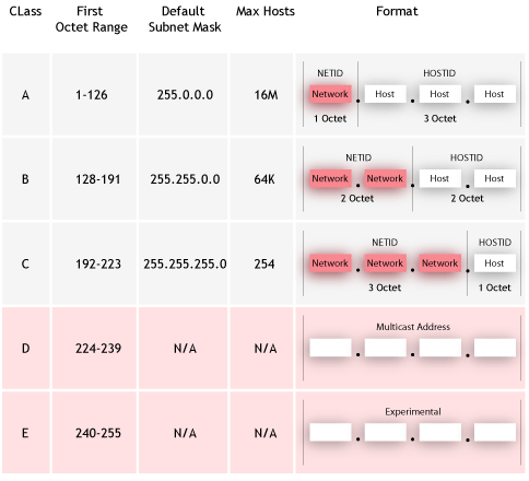
NETWORK CLASSESS

CLASS A
~Class A addresses are assigned to networks with a very large number of hosts. The high-order bit in a class A address is always set to 0. The next seven bits (completing the first octet) complete the network ID. The remaining 24 bits (the last three octets) represent the host ID. This allows for 126 networks and 16,777,214 hosts per network.


                                                        100.100.123.123
         
                                          PREFIX/FIRST        HOST


CLASS B

~Class B addresses are assigned to medium-sized to large-sized networks. The two high-order bits in a class B address are always set to binary 1 0. The next 14 bits (completing the first two octets) complete the network ID. The remaining 16 bits (last two octets) represent the host ID. This allows for 16,384 networks and 65,534 hosts per network.


                                                     100.100.123.123
         
                                          PREFIX/FIRST        HOST


CLASS C


~Class C addresses are used for small networks. The three high-order bits in a class C address are set to binary 1 1 0. The next 21 bits (completing the first three octets) complete the network ID. The remaining 8 bits (last octet) represent the host ID. This allows for 2,097,152 networks and 254 hosts per network.


                                                    100.100.123.123
         
                                          PREFIX/FIRST        HOST


CLASS D

~Class D addresses are reserved for IP multicast addresses. The four high-order bits in a class D address are always set to binary 1 1 1 0. The remaining bits are for the address that interested hosts recognize. Microsoft supports class D addresses for applications to multicast data to multicast-capable hosts on an internetwork.

CLASS E
  • binary add start with 1111
  • decimal number can be anywhere from 240 to 255
  • used for experimentation.
never have been documented or utilized in a standard way


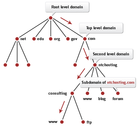
DOMAIN NAME SYSTEM (DNS)

  • Internet service that translate domain names like www.hotwired.com into numerical IP add (204.62.131.129) which computer on the net use to communicate with each other
  • Internet naming scheme which consist of a hierarchical sequence of names
  • from the most specific to the most general (left to rigth),
  • separate by dots (emoe.gov.my)
domain name are alphabetic (easeir to rememner)


INTERNET SERVICE PROVIDER (ISP)


  • Short for Internet Service Provider, it refers to a computer access to the Internet. The service provider usually provides a software package,username and password. You can then log on to the Internet and browse the World Wide Web and send and receive e-mail. ISPs also serve large companies, providing a direct connection from the company's networks to the Internet. ISPs.


  • An ISP is a company that provides individuals and other companies access to the Internet and other related services such as Web site building and virtual hosting. An ISP has the equipment and the telecommunication line access required to have a point-of-presence on the Internet for the geographic area served. The larger ISPs have their own high-speed leased lines so that they are less dependent on the telecommunication providers and can provide better service to their customers.


HTTP  (Hypertext Transfer Protocol)


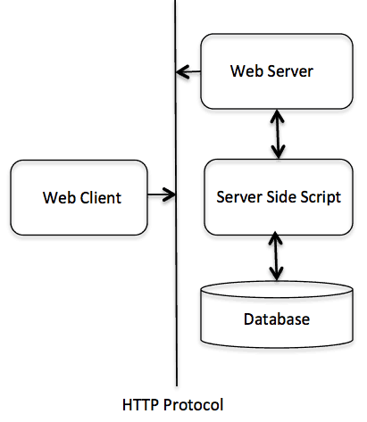
HTTP defines how messages are formatted and transmitted, and what actions Web servers and browsers should take in response to various commands. For example, when you enter a URL in your browser, this actually sends an HTTP command to the Web server directing it to fetch and transmit the requested Web page.
The other main standard that controls how the World Wide Web works is HTML, which covers how Web pages are formatted and displayed.
HTTP is called a stateless protocol because each command is executed independently, without any knowledge of the commands that came before it. This is the main reason that it is difficult to implement Web sites that react intelligently to user input. This shortcoming of HTTP is being addressed in a number of new technologies, including ActiveX, Java, JavaScript and cookies.

HTTP is connectionless: After a request is made, the client disconnects from the server and waits for a response. The server must re-establish the connection after it process the request.:-

  •  HTTP is media independent: Any type of data can be sent by HTTP as long as both the client and server know how to handle the data content. How content is handled is determined by the MIME specification.
  • HTTP is stateless: This is a direct result of HTTP's being connectionless. The server and client are aware of each other only during a request. Afterwards, each forgets the other. For this reason neither the client nor the browser can retain information between different request across the web pages.





Tuesday, May 15, 2012

UNBOUNDED MEDIA


UNBOUNDED / UN GUIDED MEDIA

Unbounded / Unguided media or wireless media doesn't use any physical connectors between the two devices communicating. Usually the transmission is send through the atmosphere but sometime it can be just across the rule. Wireless media is used when a physical obstruction or distance blocks are used with normal cable media. The three types of wireless media are:
  • RADIO WAVES
  • MICRO WAVES
  • INFRARED WAVES
1. RADIO WAVES:-
It has frequency between 10 K Hz to1 G Hz. Radio waves has the following types.
  • Short waves
  • VHF (Very High Frequency)
  • UHF (Ultra High Frequency)
SHORT WAVES:-
There are different types of antennas used for radio waves. Radio waves transmission can be divided into following categories.
  • LOW POWER, SINGLE FREQUENCY.
  • HIGH POWER, SINGLE FREQUENCY
  1. LOW POWER , SINGLE FREQUENCY:-
As the name shows this system transmits from one frequency and has low power out. The normal operating ranges on these devices are 20 to 25 meter.
CHARACTERISTICS LOW POWER , SINGLE FREQUENCY:-
  • Low cost
  • Simple installation with pre-configured
  • 1 M bps to 10 M bps capacity
  • High attenuation
  • Low immunity to EMI
2. HIGH POWER, SINGLE FREQUENCY:-
This is similar to low power single frequency. These devices can communicate over greater distances.
CHARACTERISTICS HIGH POWER, SINGLE FREQUENCY:-
  • Moderate cost
  • Easier to install than low power single frequency
  • 1 Mbps to 10 Mbps of capacity
  • Low attenuation for long distances
  • Low immunity to EMI

MICRO WAVES
Micro waves travels at high frequency than radio waves and provide through put as a wireless network media. Micro wave transmission requires the sender to be inside of the receiver.
Following are the types of Micro waves.
  1. · Terrestrial Micro waves
  2. · Satellite Micro waves
1. Terrestrial Micro waves:-
Terrestrial Micro waves are used are used to transmit wireless signals across a few miles. Terrestrial system requires that direct parabolic antennas can be pointed to each other. These systems operate in a low Giga Hertz range.
CHARACTERISTICS of Terrestrial Micro waves:-
  • Moderate to high cost.
  • Moderately difficult installation
  • 1 M bps to 10 M bps capacity
  • Variable attenuation
  • Low immunity to EMI


Satellite Micro waves
The main problem with aero wave communication is the curvature of the earth, mountains & other structure often block the line of side. Due to this reason, many repeats are required for long distance which increases the cost of data transmission between the two points. This problem is recommended by using satellites.
Satellite micro wave transmission is used to transmit signals through out the world. These system use satellites in orbit about 50,000 Km above the earth. Satellite dishes are used to send the signals to the satellite where it is again send back down to the receiver satellite. These transmissions also use directional parabolic antenna’ with in line of side.
In satellite communication micro wave signals at 6 GHz is transmitted from a transmitter on the earth through the satellite position in space. By the time signal reaches the satellites becomes weaker due to 50,000 Km distance. The satellite amplifies week signals and transmits it back to the earth at the frequency less than 6 GHz.
Characteristics Satellite Micro waves:
  • High cost
  • Extremely difficult and hare installation.
  • Variable attenuation.
  • Low immunity to EMI
  • High security needed because a signal send to satellite is broadcasts through all receivers with in satellite.


WIFI :-

Fairly recently the IEEE 802.11 standard became more popular as it suites mobile computing devices really well. The IEEE 802.11 standard is another term for WiFi essentially is wireless networking. This standard allows two computers that have wireless NICs to communicate with one another with no strings (wires) attached. This standard makes use of radio waves that are transmitted through the air to communicate. Speeds of either 54 Mbps or 108 Mbps are supported but higher speeds are in the pipeline. 


IEEE (Institute of Electrical and Electronics Engineers)
IEEE is the world’s largest professional association dedicated to advancing technological innovation and excellence for the benefit of humanity. IEEE and its members inspire a global community through IEEE's highly cited publications, conferences, technology standards, and professional and educational activities.

IEEE, pronounced "Eye-triple-E", stands for the Institute of Electrical and Electronics Engineers. The association is chartered under this name and it is the full legal name. To learn more about association's name


Difference Between 3G And 4G


Cellular phone

Cellular telephone, sometimes called mobile telephone, is a type of short-wave analog ordigital telecommunication in which a subscriber has a wireless connection from a mobile telephone to a relatively nearby transmitter. The transmitter's span of coverage is called acell. Generally, cellular telephone service is available in urban areas and along major highways. As the cellular telephone user moves from one cell or area of coverage to another, the telephone is effectively passed on to the local cell transmitter.
A cellular telephone is not to be confused with a cordless telephone (which is simply a phone with a very short wireless connection to a local phone outlet).


Uplink and downlink


In satellite telecommunication, a downlink is the link from a satellite down to one or more ground stations or receivers, and an uplink is the link from a ground station up to a satellite. Some companies sell uplink and downlink services to television stations, corporations, and to other telecommunication carriers. A company can specialize in providing uplinks, downlinks, or both.
The following table shows the main frequency bands used for satellite links.

Frequency Band
Downlink
Uplink
C
3,700-4,200 MHz
5,925-6,425 MHz
Ku
11.7-12.2 GHz
14.0-14.5 GHz
Ka
17.7-21.2 GHz
27.5-31.0 GHz

The C band is the most frequently used. The Ka and Ku bands are reserved exclusively for satellite communication but are subject to rain attenuation. Some satellites carry transponders for both C and Ku bands.


Radio frequency (RF) 
is a rate of oscillation in the range of about 3 kHz to 300 GHz, which corresponds to the frequency of radio waves, and the alternating currents which carry radio signals. RF usually refers to electrical rather than mechanical oscillations, although mechanical RF systems do exist


Infrared
Infrared frequencies are just below visible light. These high frequencies allow high sped data transmission. This technology is similar to the use of a remote control for a TV. Infrared transmission can be affected by objects obstructing sender or receiver. These transmissions fall into two categories.
  1. Point to point
  2. Broadcast
(i) Point to Point: - Point to point infrared transmission signal directly between two systems. Many lap top system use point to pint transmission. These systems require direct alignment between many devices.
Characteristics of Point to point:-
  • Wide range of cost
  • Moderately easy installation.
  • 100 k bps to 16 Mb of capacity.
  • Variable attenuation.
  • High immunity to EMI
(i) Broad Cast: - These infrared transmission use sprayed signal, one broad cast in all directions instead of direct beam. This help to reduce the problems of proper alignment and abstraction. It also allows multiple receiver of signal
Characteristics of Broad Cast:-
  • In expensive.
  • Single installation.
  • 1M bps capacity.
  • Variable attenuation.

Tuesday, May 1, 2012

Cabling


Cable is the medium through which information usually moves from one network device to another. There are several types of cable which are commonly used with LANs. In some cases, a network will utilize only one type of cable, other networks will use a variety of cable types. The type of cable chosen for a network is related to the network's topology, protocol, and size. Understanding the characteristics of different types of cable and how they relate to other aspects of a network is necessary for the development of a successful network.


The following sections discuss the types of cables used in networks:
  • Unshielded Twisted Pair (UTP) Cable
  • Shielded Twisted Pair (STP) Cable
  • Coaxial Cable
  • Fiber Optic Cable

UNSHIELDED TWISTED PAIR (UTP)


The standard connector for unshielded twisted pair cabling is an RJ-45 connector. This is a plastic connector that looks like a large telephone-style connector (See fig. 2). A slot allows the RJ-45 to be inserted only one way. RJ stands for Registered Jack, implying that the connector follows a standard borrowed from the telephone industry. This standard designates which wire goes with each pin inside the connector.
  

CategorySpeedUse
11 MbpsVoice Only (Telephone Wire)
24 MbpsLocalTalk & Telephone (Rarely used)
316 Mbps10BaseT Ethernet
420 MbpsToken Ring (Rarely used)
5100 Mbps (2 pair)100BaseT Ethernet
1000 Mbps (4 pair)Gigabit Ethernet
5e1,000 MbpsGigabit Ethernet
610,000 MbpsGigabit Ethernet


SHIELDED TWISTED PAIR (STP) 


The standard connector for unshielded twisted pair cabling is an RJ-45 connector. This is a plastic connector that looks like a large telephone-style connector (See fig. 2). A slot allows the RJ-45 to be inserted only one way. RJ stands for Registered Jack, implying that the connector follows a standard borrowed from the telephone industry. This standard designates which wire goes with each pin inside the connector.
  Although UTP cable is the least expensive cable, it may be susceptible to radio and electrical frequency interference (it should not be too close to electric motors, fluorescent lights, etc.). If you must place cable in environments with lots of potential interference, or if you must place cable in extremely sensitive environments that may be susceptible to the electrical current in the UTP, shielded twisted pair may be the solution. Shielded cables can also help to extend the maximum distance of the cables.

Shielded twisted pair cable is available in three different configurations:


  1. Each pair of wires is individually shielded with foil.
  2. There is a foil or braid shield inside the jacket covering all wires (as a group).
  3. There is a shield around each individual pair, as well as around the entire group of wires (referred to as double shield twisted pair).


COAXIAL CABLE


Coaxial lines confine the electromagnetic wave to the area inside the cable, between the center conductor and the shield. The transmission of energy in the line occurs totally through the dielectric inside the cable between the conductors. Coaxial lines can therefore be bent and twisted (subject to limits) without negative effects, and they can be strapped to conductive supports without inducing unwanted currents in them.
The most common use for coaxial cables is for television and other signals with bandwidth of multiple megahertz. Although in most homes coaxial cables have been installed for transmission of TVsignals, new technologies (such as the ITU-T G.hn standard) open the possibility of using home coaxial cable for high-speed home networking applications (Ethernet over coax).
In the 20th century they carried long distance telephone connections.

 PATCH CABLE
A patch cable is an electrical or optical cable, used to connect one electronic or optica computer, or switch to router) are connected with patch cords, and it works. It is a very fast connection speed. Patch cords are usually produced in many different colors so as to be easily distinguishable,and are relatively short, perhaps no longer than two metres.

ETHERNET CROSSOVER CABLE
An Ethernet crossover cable is a type of Ethernet cable used to connect computing devices together directly where they would normally be connected via a network switch, hub or router, such as directly connecting two personal computers via their network adapters. Cross Cable is used to connect the same devices such as pc to pc, hub to hub, switch to switch etc.

POWER LINE
Although power wires are not designed for networking applications, new technologies like Power line communication allows these wires to also be used to interconnect home computers, peripherals or other networked consumer products. On December 2008, the ITU-T adopted Recommendation G.hn/G.9960 as the first worldwide standard for high-speed powerline communications. G.hn also specifies communications over phonelines and coaxial wiring.

FIBER OPTIC CABLE


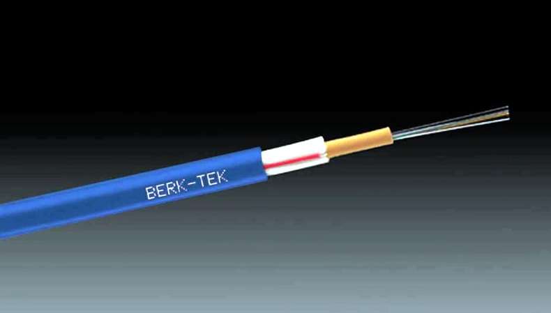
Fiber optic cabling consists of a center glass core surrounded by several layers of protective materials. It transmits light rather than electronic signals eliminating the problem of electrical interference. This makes it ideal for certain environments that contain a large amount of electrical interference. It has also made it the standard for connecting networks between buildings, due to its immunity to the effects of moisture and lighting.
Fiber optic cable has the ability to transmit signals over much longer distances than coaxial and twisted pair. It also has the capability to carry information at vastly greater speeds. This capacity broadens communication possibilities to include services such as video conferencing and interactive services. The cost of fiber optic cabling is comparable to copper cabling; however, it is more difficult to install and modify. 10BaseF refers to the specifications for fiber optic cable carrying Ethernet signals.
The center core of fiber cables is made from glass or plastic fibers. A plastic coating then cushions the fiber center, and kevlar fibers help to strengthen the cables and prevent breakage. The outer insulating jacket made of teflon or PVC.


Wednesday, March 28, 2012

WEEK 6

WEEK 6- NETWORK TOPOLOGY


What is a Topology?

The physical topology of a network refers to the configuration of cables, computers, and other peripherals. Physical topology should not be confused with logical topology which is the method used to pass information between workstations. Logical topology was discussed in the Protocol chapter.

linear Bus

Now that you know how topologies can affect networks, it's time to learn more about the different types of typologies. The term "linear" refers to a line, and the linear bus is a network configuration in which each computer is connected to the next in a (more or less) straight line. A small bus network is shown in the graphic below
One important characteristic of the linear bus is that it has a beginning and an end. When computers are cabled in a line, the signal travels down the cable. When it reaches the end, it can "bounce" back (this is called signal bounce), interfering with network communications. To prevent this, a bus network must be terminated; that is, small devices called terminators are placed at both ends of the bus.


Function of  terminator:
  • To prevent signals from being echoed back through the network
  •  small devices called terminators are placed at both ends of the bus
 advantages
  • Simple set-up
  • Least expensive layout
  • Uses inexpensive thin coax cable
  • Uses smallest amount of cable
  • Doesn't require a hub
  • Appropriate for small networks
  • For instance, a temporary training room that is set up and torn down quickly


disadvantages
  • Slow
  • Vulnerable to attenuation, or the loss of signal strength over distance
  • Inappropriate for large networks
  • Less fault tolerant


STAR

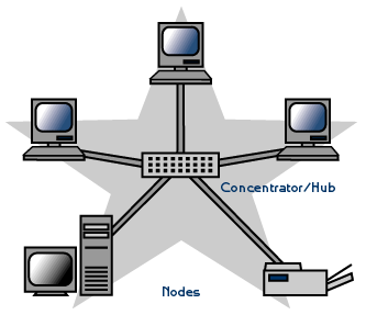
A star topology is designed with each node (file server, workstations, and peripherals) connected directly to a central network hub, switch, or concentrator.

Data on a star network passes through the hub, switch, or concentrator before continuing to its destination. The hub, switch, or concentrator manages and controls all functions of the network. It also acts as a repeater for the data flow. This configuration is common with twisted pair cable; however, it can also be used with coaxial cable or fiber optic cable.


advantages

  • Easy to install and wire.
  • No disruptions to the network when connecting or removing devices.
  • Easy to detect faults and to remove parts.
disadvantages

  • Requires more cable length than a linear topology.
  • If the hub, switch, or concentrator fails, nodes attached are disabled.
  • More expensive than linear bus topologies because of the cost of the hubs, etc.

STAR-WIRED

The standard for the Token Ring protocol is Institute of Electrical and Electronics Engineers (IEEE) 802.5. The Fiber Distributed-Data Interface (FDDI) also uses a Token Ring protocol.
A star-wired ring topology may appear (externally) to be the same as a star topology. Internally, the MAU (multistation access unit) of a star-wired ring contains wiring that allows information to pass from one device to another in a circle or ring (See fig. 3). The Token Ring protocol uses a star-wired ring topology.


  • Uses physical layout of a star topology with ring topology data transmission method
  • Data is sent around the star in a circular fashion (dotted orange in figure)
  • This hybrid technology has the fault tolerance of star topology and, ...
  • in Token Ring networks, reliability of token passing
  • Groups of nodes are connected to hubs wich are then networked on a single bus
  • Used to cover longer distances
  • Also used to interconnect, or isolate, different network segments
  • Expensive, requires more cable and more hubs
  • Modern Ethernet, and its faster cousins, are set up using this topology


TOKAN RING

A Token Ring network is a local area network (LAN) in which all computers are connected in a ring or star topology and a bit- or token-passing scheme is used in order to prevent the collision of data between two computers that want to send messages at the same time. The Token Ring protocol is the second most widely-used protocol on local area networks afterEthernet. The IBM Token Ring protocol led to a standard version, specified as IEEE 802.5. Both protocols are used and are very similar. The IEEE 802.5 Token Ring technology provides for data transfer rates of either 4 or 16 megabits
per second. Very briefly, here is how it works:
  1. Empty information frames are continuously circulated on the ring.
  2. When a computer has a message to send, it inserts a token in an empty frame (this may consist of simply changing a 0 to a 1 in the token bit part of the frame) and inserts a message and a destination identifier in the frame.
  3. The frame is then examined by each successive workstation. If the workstation sees that it is the destination for the message, it copies the message from the frame and changes the token back to 0.
  4. When the frame gets back to the originator, it sees that the token has been changed to 0 and that the message has been copied and received. It removes the message from the frame.
  5. The frame continues to circulate as an "empty" frame, ready to be taken by a workstation when it has a message to send.
The token scheme can also be used with bus topology LANs.
The standard for the Token Ring protocol is Institute of Electrical and Electronics Engineers (IEEE) 802.5. The Fiber Distributed-Data Interface (FDDI) also uses a Token Ring protocol.


l


TREE

A tree topology combines characteristics of linear bus and star topologies. It consists of groups of star-configured workstations connected to a linear bus backbone cable (See fig. 3). Tree topologies allow for the expansion of an existing network, and enable schools to configure a network to meet their needs.


advantages
  • Point-to-point wiring for individual segments.
  • Supported by several hardware and software venders.
disadvantages

  • Overall length of each segment is limited by the type of cabling used.
  • If the backbone line breaks, the entire segment goes down.
  • More difficult to configure and wire than other topologies.


Physical TopologyCommon CableCommon Protocol
Linear BusTwisted Pair
Coaxial
Fiber
Ethernet
StarTwisted Pair
Fiber
Ethernet
TreeTwisted Pair
Coaxial
Fiber
Ethernet